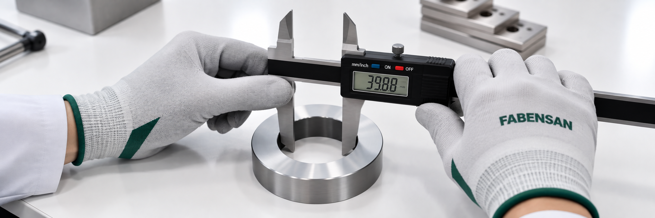
What Is Kerf in Laser Cutting and Why Does It Matter?
When a part is produced using laser cutting, there can be small dimensional differences between the technical drawing and the physical part. One of the important concepts to understand when designing laser-cut parts is kerf. Kerf refers to the width of material removed during the cutting process. Simply put, the path followed by the laser beam does not have zero width. During cutting, a small amount of material is removed from the cutting zone, creating a cut with a specific width. Kerf is particularly important when designing precision parts, components that fit together, and parts manufactured with tight tolerances. How Is Kerf Created? During laser cutting, the laser beam is focused onto a specific point on the material and moves along the cutting path. The energy generated by the laser processes the material while a certain amount of material is removed from the cutting zone. The assist gas also helps remove molten material generated during the cutting process. As a result, the physical path created by the laser is not simply an infinitely thin line. The width of this cutting path is known as kerf. What Factors Affect Kerf? Kerf is not a fixed value. The width of the cutting path can change depending on several different factors. The main factors include: * Material type * Material thickness * Laser cutting parameters * Cutting speed * Laser beam characteristics * Focus position * Nozzle selection * Assist gas * Gas pressure The kerf value can change when the same part is produced using different materials or different cutting parameters. For this reason, kerf should be evaluated under the actual production conditions, especially for precision manufacturing projects. How Does Kerf Affect Part Dimensions? Because kerf determines how much material is removed along the cutting path, it can affect the final dimensions of a part. This becomes particularly important for small parts, narrow slots, or components designed to fit together. For example, consider two parts that need to fit into each other. If the opening in one part is designed too close to the dimensions of the mating part without considering kerf and manufacturing tolerances, the components may not fit together as intended. For this reason, kerf and manufacturing tolerances should be considered together when designing precision-fit components. Is Kerf the Same as Tolerance? No. Kerf and tolerance are two different concepts. Kerf refers to the width of material removed during the cutting process. Tolerance refers to the acceptable deviation from a part's nominal dimension. For example, if a dimension is specified as 100 mm, the manufacturing tolerance defines the acceptable range around that nominal dimension. Kerf, on the other hand, relates to the physical cutting path created by the laser. Although these two concepts are related during the design and manufacturing process, they should not be used interchangeably. Why Is Kerf Important for Interlocking Parts? Parts that are designed to fit or interlock with each other require particular attention to kerf. Examples include: * Slot-together sheet metal parts * Sheet metal assemblies * Interlocking components * Self-locking sheet metal structures * Jigs * Fixtures In these applications, the components may need to fit together precisely. Considering kerf, tolerances, and material characteristics together can help ensure that parts can be assembled as intended. How Should Kerf Be Considered in Part Design? There is no single standard kerf value that applies to every laser cutting project. This is because cutting conditions can vary from one project to another. For precision-fit components, it is therefore better to use values determined according to the actual production conditions and the capabilities of the manufacturer. For prototype projects, producing and inspecting an initial part can be useful. If necessary, the design can then be adjusted before moving into larger-scale production. This approach can help identify potential assembly issues before they affect a larger production run. The Relationship Between Kerf and Nesting Kerf can affect not only part dimensions but also how material is arranged on a sheet. During the nesting process, multiple parts are positioned on the same sheet to optimize material usage. A suitable distance needs to be maintained between cutting paths. This distance can depend on factors such as: * Cutting path * Part geometry * Material * Cutting conditions * Heat effects Well-planned nesting can help ensure that parts are cut correctly while also making efficient use of the available material. Is Kerf the Same for Every Laser Cutting Process? No. Kerf can vary depending on the production conditions. Different materials, thicknesses, and cutting parameters can result in different kerf values. For this reason, a kerf value used for one project should not automatically be applied to another project. For parts requiring precise fits, the actual production conditions should always be taken into consideration. Tips for Considering Kerf in Laser Cutting Design When designing parts for laser cutting, consider the following: * Check precision-fit components before production. * Clearly specify the material type and thickness. * Define tolerances for critical dimensions. * Check whether very small gaps are suitable for manufacturing. * Consider producing a prototype before starting full production. * Take the manufacturer's recommended cutting conditions into account. These checks can help reduce potential manufacturing and assembly issues, particularly for parts that need to fit together. Laser Cutting with Fabensan Fabensan is a digital metal manufacturing platform designed to simplify the process between technical drawings and metal production. You can submit your technical drawings in DWG, DXF, or PDF format and request a quotation for your manufacturing project. The geometry, material characteristics, and manufacturing requirements of your parts can be evaluated to determine the appropriate production method. Planning the manufacturing process from the beginning can help improve the consistency between the digital design and the physical part. Submit your technical drawing and turn your design into a manufactured part. Fabensan The Digital Ecosystem of Metal Manufacturing